Currently there are no notifications.
Profile Rail Guides - Installation and Maintenance of Linear Guides
How do you achieve the optimal combination of precision and efficiency in the assembly and maintenance of profile rail guides? In our blog, we highlight different installation methods, explain the difference between mounting and reference surfaces, and provide valuable tips for precise alignment. You will also learn about permissible mounting deviations and how regular maintenance or automatic lubrication concepts can affect the service life of your linear guides.
Installation methods for profile rail guides
Depending on the application and installation situation, different installation methods can be selected, which affect the motion, stability, and precision of the entire system. Whether the rails or guide carriages are movable, or whether they are mounted on the inside or outside, depends on the specific requirements. The following are some installation methods.
Rail fixed, guide carriage movable
This is the most commonly used installation method for profile rail guides. In this case, the rail is securely connected to the base structure or machine frame, while the guide carriage moves along the rail. This configuration is ideal for applications where linear movement of a machine component, workpiece, or tool is required, such as in machine tools or automation systems.

Rail movable, guide carriage fixed
In this configuration, the guide carriage remains fixed and the rail takes over the movement. This configuration is used less often, but is suitable for applications with limited space or when it is necessary to move larger components without relocating the guide carriage itself. A typical use case is the movement of doors, sliding tables, or lifting devices. A challenge with this installation method is designing the movement of the rail so that its parallelism and alignment are maintained.

Lateral mounting, concealed or external
Easily accessible carriages make maintenance and lubrication easier. This configuration also facilitates inspection of the rail and carriage for wear or damage. Concealed, internal carriages, on the other hand, are better protected from external influences such as dust, moisture, or chemicals. They are often used in environments with a high risk of contamination. The example shows a side mount with a fixed rail and a movable guide carriage.

Mounting surfaces vs. reference surfaces
Precisely manufactured mounting and reference surfaces form the basis for accurate component assembly and positioning. While mounting surfaces are primarily responsible for mechanical fastening, reference surfaces allow precise geometric alignment of the profile rail guide. The reference surfaces serve as the reference surfaces for alignment as well as for the measurements and calculations of the linear guide system.
MISUMI profile rail guides have so-called reference surface markings, i.e., special markings on the rails and guide carriages that indicate which surfaces serve as reference surfaces for the most precise alignment during assembly. These markings facilitate precise positioning of components and contribute to proper assembly.

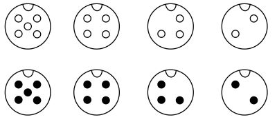
- A - Miniature Linear Guide (cost efficient),
- B - Profile rail guides (medium and high loads),
- C - Profile rail guides with plastic ball cage (medium and high loads),
- D - Profile rail guides (cost-effective / medium and high loads),
① datum markings, ② datum (polished surface), ③ narrow groove, ④ wide groove
Flatness of the mounting surface
Unevenness of the mounting surface can affect the linear guide by deforming the guide carriages. This deformation can cause excessive play, which changes the preload and causes problems. Therefore, the mounting surfaces must be clean, flat and level to ensure a uniform contact surface. Inadequate linear guide flatness directly affects load distribution and can cause uneven wear or running problems.

Mounting profile rail guides
The mounting of profile rail guides varies considerably depending on whether or not the base plate has a reference surface. Mounting with the reference surface present is the preferred method when high precision and low assembly time are required. If there is no reference surface, the installation requires careful manual alignment, which can be time-consuming and more prone to error.
Mounting with existing reference surface on the base plate
A precisely machined reference surface on the base plate serves as the basis for the exact alignment of the profile rail guide. In this method, the profile rail is first aligned with its reference edge directly on the reference surface. The profile rail is fixed in place with screws. These are gradually tightened to avoid tension.


Mounting on the base plate in the absence of a reference surface
If there is no machined reference surface, the profile rail must be aligned independently to ensure the required precision. This requires additional tools such as a ruler. The ruler is applied to the provisionally tightened rail and the fixing screws are tightened with the ruler as a reference.


For both installation methods, the parallelism must be measured after installation. Special dial indicators can be used for this.
Permissible mounting deviations
Precise mounting of profile rail guides is critical to their functionality, life and accuracy. However, some variations in rail and carriage alignment are inevitable. These permissible assembly deviations are defined by manufacturer's specifications and take into account the design tolerance of the guide as well as the requirements of the application. Permissible assembly deviations should be strictly observed.


The parallelism deviation occurs when two parallel rails are not mounted exactly in line. This forces the guide carriage to perform lateral correction movements, resulting in uneven loading and increased wear. The permissible deviation of the parallelism depends on the precision class of the guide.
The height deviation refers to the vertical deviation of the profile rail guide from the ideal mounting position. It is measured along the mounting surface and describes how much the actual height of the rail deviates from the required position. Height deviations can result from unevenness in the mounting surface, inaccurate machining of the machine structure, or manufacturing tolerances of the rail itself.
Profile Rail Guide Maintenance
Maintenance of profile rail guides is very important to ensure function and longevity. While maintenance-free linear guides, through integrated lubricants or self-lubricating materials, minimize maintenance effort and reduce downtime, conventional systems require regular inspections and relubrication. The choice between these variants depends on the specific requirements of the application.
Regular maintenance significantly extends the life of profile rail guides. The focus is on aspects such as lubrication, checking friction resistance and determining appropriate maintenance intervals. Maintenance activities help minimize wear, reduce downtime, and increase operational safety.
For more information on maintaining profile rail guides, see our article Profile Rail Guides: Types, function, service life, maintenance, alternatives.
Friction in linear guides
Friction in linear guides is caused by contact between the rolling elements and the running surfaces of the rail and the carriage. While this contact is optimized for rolling, some friction remains. Without sufficient lubrication, this friction leads to increased wear, higher energy consumption, and reduced running accuracy.
The coefficient of friction is a magnitude that describes the relationship between the friction force and the normal force. In profile rail guides, the coefficient of friction depends on material pairings, surface finish, and lubrication quality. A low coefficient of friction indicates smooth movement with low resistance.
| Version | Dynamic friction coefficient (μ) |
|---|---|
| Miniature profile rail guide | 0.004 to 0.006 |
| Profile rail guide with medium load capacity | 0.002 to 0.003 |
| Cross roller guides | 0.001 to 0.003 |
| Cross roller tables | 0.001 to 0.003 |
| Linear bearings | 0.002 to 0.003 |
| Linear ball bearing | 0.0006 to 0.0012 |
Lubrication of profile rail guides
Lubrication performs several tasks to control friction and optimize the performance of the profile rail guide. Lubricants reduce contact resistance by creating a film between the contact surfaces. Lubrication also largely prevents material contact and therefore wear. In addition, the lubricating film acts like a damping layer that reduces microvibrations.
A low-viscosity lubricant is ideal for low frictional resistance and high precision. High-viscosity lubricants or special additives are required for applications with high loads or extreme conditions. The use of scrapers or seals protects the tracks from particles that can affect lubrication and increase friction. In order to maintain a constant lubricating film, regular relubrication according to operating conditions is essential.
Lubricant selection should be based on operating conditions, load, and desired maintenance intervals. Careful consideration ensures long-lasting and trouble-free operation of the profile rail guides.
The importance of lubricating profile rail guides for service life is also demonstrated by the following article on the lubrication of ball screws.
Maintenance Intervals and Replacement Intervals
Profile rail guides are designed to ensure high precision and durability over long periods of time. Regular maintenance is essential to maintain these characteristics. Maintenance intervals depend on factors such as operating environment, loads, travel speed, and lubricant type. For example, for applications with high loads, vibrations, or dirty environments, shorter intervals are recommended.
The replacement intervals of a profile rail guide depend on its calculated service life and actual operating conditions. The rated life (based on load capacity and operating load) provides a guideline for the expected service life. Signs of replacement may include increased frictional resistance or uneven movement. In addition to unusual noise and obvious damage, replacement is also necessary in the event of repeated accuracy deviations or running inaccuracies.
Careful planning of maintenance and replacement intervals can reliably prevent unexpected failures of the entire system and the profile rail guides. While maintenance intervals ensure functionality, timely replacement extends the precision and reliability of the entire system. Precise maintenance intervals and the correct replacement time are therefore critical for all linear guide systems – from ball bearings to profile rails.