Currently there are no notifications.
Technical guide to bearing selection for rotating shafts and torsion shafts
Shafts are a key element of almost any machine. In order for these rotating and torsion-loaded components to function reliably, the bearings that carry these shafts must be perfectly matched to the respective application and installation situation. The selection of a suitable shaft bearing (rotary bearing) therefore has a significant impact on the service life and energy efficiency of a machine as well as its noise generation and maintenance requirements.
But which type of bearing is the right one for a particular shaft?
This guide shows how to select the optimal bearing solution for rotating and torsion shafts based on technical criteria and practical framework conditions.
Function and importance of shaft bearings
Shaft bearings allow for a bearing seat (a movable connection) between two elements that move relative to each other, such as a shaft and a housing. They support the shaft, hold it in position, and allow the shaft to rotate about its own longitudinal axis. The various designs differ not only in the extent to which they restrict the individual degrees of freedom (play, axial, radial, angular), but also in their operating behavior, precision, and load-bearing capacity.
Depending on the installation situation, radial forces, axial forces, or a combination of both must be absorbed by the shaft bearings. However, the positioning accuracy, friction losses and heat generation, as well as the service life and vibration behavior of the overall system, are also influenced by the shaft bearings used.
The problem:
in design terms, engineers are often faced with a situation where the shaft is already specified. The function, diameter, and material of the shaft are already defined, and the bearing must adapt to the shaft. In such cases, the inner diameter of the bearing is determined directly by the shaft dimension, while other parameters such as size, design, tolerance, sealing and lubrication, and material can be specifically selected.
What influencing factors must be considered?
Shaft bearing selection begins with the analysis of the application and the determination of the requirements to be met. These requirements determine whether radial, axial or angular contact bearings are required.
In particular, the following must be taken into account:
| Forces and directions at shaft bearing | |||||||||||||||||||||||||||||||||||||||||||||||||||||||||||||||||||||||||||||||||||||||||||||||||||
|---|---|---|---|---|---|---|---|---|---|---|---|---|---|---|---|---|---|---|---|---|---|---|---|---|---|---|---|---|---|---|---|---|---|---|---|---|---|---|---|---|---|---|---|---|---|---|---|---|---|---|---|---|---|---|---|---|---|---|---|---|---|---|---|---|---|---|---|---|---|---|---|---|---|---|---|---|---|---|---|---|---|---|---|---|---|---|---|---|---|---|---|---|---|---|---|---|---|---|---|
| Force | Direction | Typical cause | Detail image | ||||||||||||||||||||||||||||||||||||||||||||||||||||||||||||||||||||||||||||||||||||||||||||||||
| Radial forces | Radial / perpendicular to shaft axis | Belt tension, Weight, Imbalance |
 |
||||||||||||||||||||||||||||||||||||||||||||||||||||||||||||||||||||||||||||||||||||||||||||||||
| Axial forces | Axial / parallel to shaft axis | Axial loads, helical gears |  |
||||||||||||||||||||||||||||||||||||||||||||||||||||||||||||||||||||||||||||||||||||||||||||||||
| Combined forces |
Perpendicular and parallel to shaft axis | Almost always occurs in practice |  |
||||||||||||||||||||||||||||||||||||||||||||||||||||||||||||||||||||||||||||||||||||||||||||||||
| |||||||||||||||||||||||||||||||||||||||||||||||||||||||||||||||||||||||||||||||||||||||||||||||||||
Speed, load and fluctuating load
High speeds require low-friction shaft bearings. Due to their low contact area between the bearing ring and rolling element, rolling bearings are suitable here.
High loads, such as those found in presses or gearboxes, favor the use of roller bearings or needle bearings, since forces acting on their linear load-bearing surface can be better distributed.
| Contact area of shaft bearings | |||
|---|---|---|---|
| Bearing type | Contact area (simplified) |
Typical speed |
Load capacity |
| Ball bearings |  |
High | Low to medium |
| Roller bearings |  |
Medium | High |
| Needle bearings |  |
Medium | Very high |
| Plain bearings | Speed and load depend on material and friction. The PV value indicates suitability of pressure-speed ratio. | ||
If alternating loads or shock loads are to be expected in the application, the shaft bearings must also be designed for this purpose. Tapered roller bearings or angular contact ball bearings with high internal stability are often advantageous here. These can be operated with clearance or with preload thanks to their adjustability.
Fatigue resistance (material) is also critical for high-frequency load changes (vibrations).
For detailed information on the properties and differences of plain and rolling bearings, please refer to our posts Plain bearings in practice and Differences between ball bearings and plain bearings.
Operating temperature
The effect of the operating temperature on the lubrication and running characteristics of the shaft bearings is not to be ignored. At temperatures above 70 °C, the lubrication behavior and material properties of many lubricants change. If higher operating temperatures are to be expected, high-temperature greases can be a solution.
The material of the bearing (plastic, steel, ceramic) and its temperature resistance must also be considered.
Installation conditions, space requirements and integration into the design
The possibilities for integrating the shaft bearings within the machine should also be considered. In compact systems, the axial height and width of the shaft bearings play an important role; good access to the installed shaft bearings should not be underestimated, as it has a strong influence on subsequent maintenance options and maintenance costs. The different mounting types of housing bearings: pillow block bearings, flanged bearings or integrated bearing solutions offer different possibilities here. While finished housing units such as pillow block bearings or flanged bearings allow for easy integration, individual designs allow the bearing to be integrated directly into the component.
Fit selection
in our example, the shaft and thus the nominal diameter have already been selected. The nominal diameter of the inner ring of the bearing is thus fixed. There are tolerance tables for bearing inner rings and bearing outer rings.
For the integration, 4 tolerance field positions must be considered:
- Tolerance field position of the shaft
- Tolerance field position of the bearing inner ring
- Tolerance field position of the bearing outer ring
- Tolerance field position of the bore in the housing
Common market tolerance field positions for shafts are g6, h6, h7.
A typical tolerance class for the housing bore is H7, resulting in a clearance fit in combination with the outer ring tolerance. The advantage of this fit is easy installation. If it is necessary to fix the bearing outer ring, an anaerobic adhesive is recommended.
The tolerance field positions for bearing outer and bearing inner rings of radial bearings are defined according to JIS or ISO. The accuracy classes are defined here (e.g. P0).
Tolerance classes for external dimensions of the bearing are typically specified in P-classes (precision classes). The tolerance class for internal clearance is typically given as C-classes (clearance classes),
The selected coupling of the fit between the shaft and bearing as well as the bearing and housing results in the overall bearing clearance in connection with all actual tolerances.
For more information, see our articles: Principles of dimensional tolerances and fit selection and Fit types and tolerances – An overview.
| Tolerances for radial bearings (class 0) - inner ring (unit: μm) - excerpt from JIS B 1514 | |||||||||||||
|---|---|---|---|---|---|---|---|---|---|---|---|---|---|
| d Nominal diameter Inner ring in mm |
dmp | Diameter series | Vdmp | Kia | One bearing | Several bearings | V Bs | ||||||
| 9 | 0, 1 | 2, 3, 4 | Bs | Bs | |||||||||
| Vdp | |||||||||||||
| From | To | From | To | Max. | Max. | Max. | From | To | From | To | Max. | ||
| 0.6(1) | 2.5 | 0 | -8 | 10 | 8 | 6 | 6 | 10 | 0 | -40 | − | − | 12 |
| 2.5 | 10 | 0 | -8 | 10 | 8 | 6 | 6 | 10 | 0 | -120 | 0 | -250 | 15 |
| 10 | 18 | 0 | -8 | 10 | 8 | 6 | 6 | 10 | 0 | -120 | 0 | -250 | 20 |
| 18 | 30 | 0 | -10 | 13 | 10 | 8 | 8 | 13 | 0 | -120 | 0 | -250 | 20 |
| 30 | 50 | 0 | -12 | 15 | 12 | 9 | 9 | 15 | 0 | -120 | 0 | -250 | 20 |
| 50 | 80 | 0 | -15 | 19 | 19 | 11 | 11 | 20 | 0 | -150 | 0 | -380 | 25 |
| 80 | 120 | 0 | -20 | 25 | 25 | 15 | 15 | 25 | 0 | -200 | 0 | -380 | 25 |
| 120 | 180 | 0 | -25 | 31 | 31 | 19 | 19 | 30 | 0 | -250 | 0 | -500 | 30 |
| 180 | 250 | 0 | -30 | 38 | 38 | 23 | 23 | 40 | 0 | -300 | 0 | -500 | 30 |
| 250 | 315 | 0 | -35 | 44 | 44 | 26 | 26 | 50 | 0 | -350 | 0 | -500 | 35 |
| 315 | 400 | 0 | -40 | 50 | 50 | 30 | 30 | 60 | 0 | -400 | 0 | -630 | 40 |
| 400 | 500 | 0 | -45 | 56 | 56 | 34 | 34 | 65 | 0 | -450 | − | − | 50 |
| 500 | 630 | 0 | -50 | 63 | 63 | 38 | 38 | 70 | 0 | -500 | − | − | 60 |
| 630 | 800 | 0 | -75 | − | − | − | − | 80 | 0 | -750 | − | − | 70 |
| 800 | 1000 | 0 | -100 | − | − | − | − | 90 | 0 | -1000 | − | − | 80 |
| 1000 | 1250 | 0 | -125 | − | − | − | − | 100 | 0 | -1250 | − | − | 100 |
| 1250 | 1600 | 0 | -160 | − | − | − | − | 120 | 0 | -1600 | − | − | 120 |
| 1600 | 2000 | 0 | -200 | − | − | − | − | 140 | 0 | -2000 | − | − | 140 |
| Tolerances for radial bearings (class 0) - outer ring (unit: μm) - excerpt from JIS B 1514 | |||||||||||||
|---|---|---|---|---|---|---|---|---|---|---|---|---|---|
| D Nominal diameter Outer ring in mm |
Dmp | Open bearing | Closed bearing, Shielded bearing |
(4) VDmp |
Kea | Cs | VCs | ||||||
| Diameter series | |||||||||||||
| 9 | 0, 1 | 2, 3, 4 | 2, 3, 4 | ||||||||||
| VDp | |||||||||||||
| From | To | From | To | Max. | Max. | Max. | Max. | From | To | Max. | |||
| 2.5(3) | 6 | 0 | −8 | 10 | 8 | 6 | 10 | 6 | 15 | Depends on tolerance Bs to d of same bearing | Depends on tolerance Bs to d of same bearing |
||
| 6 | 18 | 0 | −8 | 10 | 8 | 6 | 10 | 6 | 15 | ||||
| 18 | 30 | 0 | −9 | 12 | 9 | 7 | 12 | 7 | 15 | ||||
| 30 | 50 | 0 | −11 | 14 | 11 | 8 | 16 | 8 | 20 | ||||
| 50 | 80 | 0 | −13 | 16 | 13 | 10 | 20 | 10 | 25 | ||||
| 80 | 120 | 0 | −15 | 19 | 19 | 11 | 26 | 11 | 35 | ||||
| 120 | 150 | 0 | −18 | 23 | 23 | 14 | 30 | 14 | 40 | ||||
| 150 | 180 | 0 | −25 | 31 | 31 | 19 | 38 | 19 | 45 | ||||
| 180 | 250 | 0 | −30 | 38 | 38 | 23 | − | 23 | 50 | ||||
| 250 | 315 | 0 | −35 | 44 | 44 | 26 | − | 26 | 60 | ||||
| 315 | 400 | 0 | −40 | 50 | 50 | 30 | − | 30 | 70 | ||||
| 400 | 500 | 0 | −45 | 56 | 56 | 34 | − | 34 | 80 | ||||
| 500 | 630 | 0 | −50 | 63 | 63 | 38 | − | 38 | 100 | ||||
| 630 | 800 | 0 | −75 | 94 | 94 | 55 | − | 55 | 120 | ||||
| 800 | 1000 | 0 | −100 | 125 | 125 | 75 | − | 75 | 140 | ||||
| 1000 | 1250 | 0 | −125 | − | − | − | − | − | 160 | ||||
| 1250 | 1600 | 0 | −160 | − | − | − | − | − | 190 | ||||
| 1600 | 2000 | 0 | −200 | − | − | − | − | − | 220 | ||||
| 2000 | 2500 | 0 | −250 | − | − | − | − | − | 250 | ||||
Axial bearing retention
When combining the shaft, bearing, and housing, axial displacement should be prevented. Thus, at least one side should be designed as a fixed bearing in the case of a double bearing of a shaft.
For this purpose, there are various options for the two interfaces outer ring housing and inner ring shaft.
The following retaining elements or securing methods are available, among others:
- form-fitting retainers such as: snap rings, retaining rings, lock washer, or locknuts.
- force-locking retainers such as: claw clamping discs, set collars, or clamping rings
- friction-locking retainers such as: anaerobic adhesives or press fits
For more information, see our article Elements for securing axial bearings.
In addition to the design aspects and the available space, the sealing and protection of the shaft bearings should also be considered. Dust, moisture, and chips can not only have a negative impact on the lubricating behavior and running characteristics of the shaft bearings. In the worst case, they can lead to bearing damage.
Common seal types for rolling bearings are:
- Shields (Z / ZZ): single or double-sided, for dry, clean environments
- Sealing washers (RS / 2RS): protect against moisture, dust, and light splashing water
- Labyrinth seals and cover plates: for harsh industrial environments with heavy contamination
More information can be found in our article: Sealing ball bearings – Seals, sealing washers and cover washers.
Arrangement and combination options
Taking into account the shaft form and shaft dimension, as well as the available space, the shaft bearings must also meet the requirements for accuracy and load. The selection, integration and arrangement of the bearings must therefore be carefully considered.
Here are some installation examples:
Grooved ball bearing

Deep groove ball bearings are designed for high speeds. The low contact areas between the rolling elements and the raceways of the inner and outer rings result in low friction and low heat generation. They can accommodate both radial and moderate axial loads, providing a reliable solution for many applications.
However, deep groove ball bearings are less suitable for applications with high moment loads, misalignment, or axial displacements.
Angular contact bearing

Angular contact bearings are also suitable for high speeds. They can accommodate combined loads, i.e., radial and axial forces simultaneously.
However, due to their design, angular contact bearings can only be loaded axially from one direction. If the axial force is applied from the opposite direction, the bearing rings and rolling elements will shift, which can lead to bearing failure. As with all ball bearings, the load capacity is limited by the spot type contact area between the rolling elements and the raceways. If the axial force is to be accommodated in both directions, a pairwise arrangement is required.
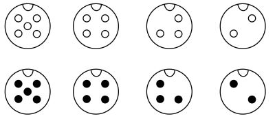
Arrangement options for angular contact ball bearings
Angular contact bearings offer an economical way to accommodate axial forces in addition to radial forces. The correct arrangement of the bearings is crucial.
In an O-arrangement (1) or X-arrangement (2), the bearings can support each other.
A parallel arrangement
(3 = tandem arrangement) can accommodate significantly higher axial forces in one direction, but does not provide a supporting effect in the opposite direction.

Self-aligning ball bearing

Self-aligning ball bearings consist of two rows of balls arranged between an inner and an outer ring. Due to their special design, the rolling elements can easily move in the axial direction, so that the bearing can self-align within a certain range in the event of misalignment.
Angular misalignments (angular deviations) can be compensated within a limited range. The same applies to radial insert ball bearings with spherical outer ring.
The raceway of the outer ring forms a domed surface, whose center of curvature is also the bearing center. The inner rings, balls, and cage can freely rotate around the ball bearing center and self-align. Self-aligning ball bearings are well suited for use on drive shafts with a tendency to bend. They are also suitable for situations where shaft and housing alignment is difficult.
")
Thrust ball bearing

Axial deep groove ball bearings – often referred to simply as thrust bearings – are used to accommodate axial forces acting on a shaft. To a small extent, they can also transmit radial forces.
Thrust ball bearings enable low-friction shaft rotary motion while maintaining high axial stability and precision.
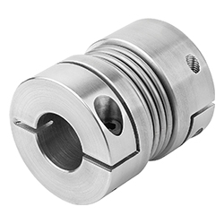
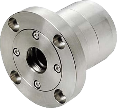
Complete shaft bearing housings
Shaft bearing housings offer the possibility of integrating finished rolling bearing positioning and alignment relatively easily into an existing system. The shaft bearing housings are usually pre-lubricated and sealed by the manufacturer. In addition, they reduce design effort and spare part procurement by providing them as finished assemblies.
In the example, a combination of 2 angular contact ball bearings and a deep groove ball bearing.

① angular contact bearing combination (fixed bearing, O-arrangement)
② deep groove ball bearing (floating bearing)
③ housing body
④ spacers*
⑤ cover
⑥ cover
⑦ sleeve for inner ring
⑧ Screw
(* not necessary with a stepped shaft)
The plain bearing as an alternative to the rolling bearing
Unlike rolling bearings, plain bearings do not work with rolling elements, but with the principle of sliding on a lubricating film. Plain bearings are low maintenance and cost effective, but are usually more susceptible to wear than rolling bearings. For very high radial loads, heavy impacts or slow movement, they can be a very good alternative to rolling bearings. For more information, see our post: Differences between ball bearings and plain bearings.
Summary - Bearing Selection Procedure
- Analysis of shaft function (rotary motion, torque, load)
- Determination of the type of load (radial, axial or combined)
- Calculation of loads and speeds
- Design definition (ball, roller, combination or plain bearings)
- Determination of fit, lubrication, and sealing
- Checking the installation conditions
- Simulation / recalculation of service life (DIN ISO 281)
- Integration into the CAD system
Practical examples
Example:
High-speed spindle with a speed of approximately 25,000 rpm and low load.
Possible application:
Angular contact ball bearing (pair arrangement) with grease filling
Example:
Drive shaft in transmission (combined load and moderate speed)
Possible application:
Tapered roller bearing (preloadable)
Example:
Conveyor roller shaft (low speed with high load in dusty environment)
Possible application:
Spherical roller bearing with labyrinth seal
Common sources of error:
- Improper fit: leads to play or crushing damage.
- Inadequate lubrication: Main cause of bearing damage.
- Misalignment: dramatically increases bearing load.
- Overload: reduces service life exponentially.
- Insufficient sealing: leads to corrosion and premature failure.
| Lager type | Example | Typical features | Section |
|---|---|---|---|
| Ball bearings | Deep groove ball bearing (e.g. DIN 625) |
• Universal use • High speeds possible • Low noise • Radial and moderate axial loads both ways |
 |
| Angular contact ball bearing (e.g. DIN 628) |
• For combined loads (radial + axial) • Axial load one direction (both in X or O setup) |
 |
|
| Four-point bearing | • Special angular contact type • Axial loads both directions, limited radial • Ideal for high precision, limited space |
 |
|
| Self-aligning ball bearing (e.g. DIN 630) |
• Compensates misalignment • Good for housing distortion or shaft deflection • Medium speed and load |
 |
|
| Thrust ball bearing (e.g. DIN 711) |
• Only axial loads • Often used with radial bearings |
 |
|
| Roller bearings | Cylindrical roller bearing (e.g. DIN 5412) |
• Very high radial capacity • Low axial capacity (special designs only) |
 |
| Tapered roller bearing (e.g. DIN 720) |
• Supports combined loads • Precise clearance setting • Often in axles and gearboxes |
 |
|
| Spherical roller bearing (e.g. DIN 635) |
• Self-aligning for misalignment • Very high load ratings • Suitable for shock loads |
 |
|
| Cross roller bearing | • Crossed cylindrical rollers • High rigidity and precision, compact • Ideal for robot axes or rotary tables |
 |
|
| Thrust roller bearing, Thrust needle bearing |
• Pure axial load, very high capacity • Used in presses, conveyors, machine tools Washer types: GS = housing side WS = shaft side LS = center for double cage or no phase offset needed |
||
| Needle bearing | • Slim design with high capacity • Ideal for limited space • Sensitive to misalignment • Often in gearboxes and shafts |
 |
|
| Combined bearings | Combination of ball and roller bearing (NKX bearing) |
• Combines advantages of used bearing types |  |