Currently there are no notifications.
Conveyor technology - Wear indicators of synchronous belts / tolerances of timing pulleys
Synchronous belts or timing belts are installed as drive elements in a wide variety of applications. They are characterized by extremely precise synchronization and efficiency. This feature is used in applications where accurate timing is important, such as positioning tasks or a conveyor belt in the packaging, food or automotive industries. However, it is particularly important in these areas to detect and correct signs of timing belt wear early. In this article, you will learn about the typical signs of wear that occur with synchronous belts and what measures you can use to specifically extend their service life.
Synchronous belt construction
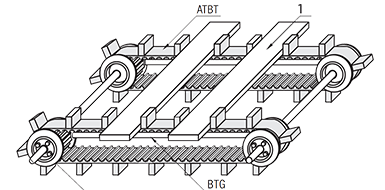
In order to be able to assess the various signs of wear, we will first look at the general design of a synchronous belt. On the inside, there are teeth at regular intervals that ensure positive engagement with a timing belt pulley. The positive engagement allows timing belts to form their own class within the mechanical power transmission. The tooth surface assumes a reinforcing role. The most important component is the tension cord. This is inside and prevents the synchronous belt from elongating. It also guarantees a uniform power transmission (see Correct selection of gearbox timing belts). Wear on the tension cord is particularly difficult to detect as it is not visible and completely embedded inside the belt.

(1) = rubber tooth body
(2) = tooth tip
(3) = tooth surface
(4) = tooth surface
(5) = tooth base
(6) = tension cord
Timing Belts: Detecting wear
Synchronous belts are subjected to mechanical, thermal, and chemical stresses during operation, which lead to progressive wear. To avoid unplanned downtime or consequential damage, e.g., in the conveyor belt drive, typical signs must be detected at an early stage.
The most common wear characteristics include:
- Cracks or visible damage to the rubber body, especially in the area of the tooth flanks and the tooth base. These are often caused by material fatigue, overload, or external influences such as oil or chemical contact.
- Abrasion or fraying of the teeth that may indicate misalignment of the belt pulleys in the timing belt or an overly tight bend radius.
- Unusual noises during operation, such as humming, squeaking, or howling, are indicative of insufficient tension or improper synchronous belt guidance.
- Jerking, vibrations, or loss of power from the driven system indicate uneven tooth engagement or worn profiles.
- A wavy running motion or inadequate interlocking with the toothed pulley negatively affects power transmission. Uneven belt tension might be responsible.
The following table shows examples of typical wear and tear of synchronous belts:
| Examples | Condition | ||||||||||||||||||||||||||||||||||||||||||||||||||||||||||||||||||||||||||||||||||||||||||||||||||
|---|---|---|---|---|---|---|---|---|---|---|---|---|---|---|---|---|---|---|---|---|---|---|---|---|---|---|---|---|---|---|---|---|---|---|---|---|---|---|---|---|---|---|---|---|---|---|---|---|---|---|---|---|---|---|---|---|---|---|---|---|---|---|---|---|---|---|---|---|---|---|---|---|---|---|---|---|---|---|---|---|---|---|---|---|---|---|---|---|---|---|---|---|---|---|---|---|---|---|---|
| 1. If tooth fabric and rubber/wire core show wear is visible. If tooth surfaces/grooves show wear and the rubber/wire core is visible. |
 |
||||||||||||||||||||||||||||||||||||||||||||||||||||||||||||||||||||||||||||||||||||||||||||||||||
| 2. If rubber on the back shows hardening cracks |  |
||||||||||||||||||||||||||||||||||||||||||||||||||||||||||||||||||||||||||||||||||||||||||||||||||
| 3. If cracks reach the rubber and are visible at tooth base |  |
||||||||||||||||||||||||||||||||||||||||||||||||||||||||||||||||||||||||||||||||||||||||||||||||||
| 4. Belt side faces damaged by wear |  |
||||||||||||||||||||||||||||||||||||||||||||||||||||||||||||||||||||||||||||||||||||||||||||||||||
| 5. If a missing tooth is visible |  |
||||||||||||||||||||||||||||||||||||||||||||||||||||||||||||||||||||||||||||||||||||||||||||||||||
| 6. If premature wear occurs on belt back |  |
||||||||||||||||||||||||||||||||||||||||||||||||||||||||||||||||||||||||||||||||||||||||||||||||||
| 7. If belt or wire core is broken |  |
||||||||||||||||||||||||||||||||||||||||||||||||||||||||||||||||||||||||||||||||||||||||||||||||||
| |||||||||||||||||||||||||||||||||||||||||||||||||||||||||||||||||||||||||||||||||||||||||||||||||||
But what are the causes of timing belt wear? In addition to the typical wear and tear over the service life, incorrect installation or application can lead to increased wear. Tooth breakage and/or tooth cracks are caused, for example, by a continuous load or undersized deflection pulleys. At this point, it would be worth considering using more durable belts (e.g. PU), larger diameter pulleys or reducing the load. Edge fraying is often caused by belt misalignment. The correct alignment of the belt drive is the remedy here. Broken teeth may indicate insufficient tension, misalignment, or an inappropriate belt tooth profile. Overall, it is recommended to recalculate the gearbox, gear ratio and transmission of the required load before using a new synchronous belt. Often, the causes are also in adjacent components such as damaged rolling bearings.
Aligning the pulley
Even minor parallelism and angle errors can lead to uneven abrasion and increased load on the timing belt. Misalignment is usually accompanied by increased noise and vibration loads as well as reduced efficiency. There are a few basic things to consider for a successful installation.
For example, the belt width affects the permissible deviation of the pulley alignment, as shown in the following table. The selection of suited, matching toothed pulleys and tension rollers is also relevant for successful installation; see our article about selecting and replacing toothed pulleys, synchronous pulleys and tension rollers.
| Series | Belt width (mm) | Deviation (tan Θ) |
|---|---|---|
| MXL XL L H S3M/S5M/S8M MTS8M T |
≤10 | 5/1000 |
| >10 ≤20 |
3/1000 | |
| >20 ≤30 |
2/1000 | |
| P2M/P3M/P5M/P8M UP5M/UP8M |
≤30 | 5/1000 |
| 1.5GT/2GT/3GT/5GT EV5GT EV8YU |
≤20 | 6/1000 |
| >20 ≤40 |
3/1000 |
It is also recommended to visually inspect the components to detect any bearing damage and contamination, so that you can repair or remove them in advance.
Also, since pulleys must be aligned parallel on the same plane, it is important to check parallelity and angular alignment. The following figure shows the ideal pulley alignment:

The ruler and cord method can be used for verification, but it is better to use modern laser alignment systems. For this purpose, a laser transmitter is attached to the pulley and a receiver is attached to the opposite pulley. The lasers can be used to detect and correct deviations immediately. Use of these systems is recommended especially for large belt drives or hard-to-reach areas. While it is expensive to purchase such a system, the long-term benefits outweigh the cost.
Common pulley assembly and alignment errors already occur during fastening. For example, failure to tighten the set screws to the correct torque may result in the set screws loosening during operation and allowing the pulley to slip out of its ideal position. The manufacturer's information on the tightening torques must therefore be strictly observed. In addition, it is possible to counteract loosening with shim rings and clamping bushes.
Premature failures and countermeasures
Premature failures often result from overload, incorrect preload, or improper handling. Excessive tension causes excessive tensile loads, and inadequate tension is associated with slippage and uneven power transmission. Dirt, dust and other foreign objects also significantly affect the service life of synchronous belts.
The table below provides an overview of several types of premature failure modes and measures that can help counteract them:
| Abnormal signs | Cause | Measures |
|---|---|---|
| Abnormal wear of belt side faces | · Pulley misalignment · Pulley shaft misalignment · Bent flanges |
· Realign · Correct shaft misalignment · Straighten flanges |
| Abnormal wear of tooth contact surface | · Overload · Belt tension too high/low |
· Use wider belt or larger pitch · Adjust belt pretension |
| Excessive belt wear at pulley contact | · Wrong pulley tooth form · Belt tension too high |
· Adjust belt pretension · Reconfigure system considering tip radius |
| Broken/missing tooth | · Pulley ⌀ too small · Small pulley ≤6 teeth in mesh · Shock load occurs |
· Change design · Increase teeth in mesh or redesign · Avoid shock load · Increase belt width |
| Separated wire core | · Overload · Wire core degraded/corroded · Foreign matter ingress · Excessive temperature |
· Change design · Check storage/shipping condition · Avoid shock load · Add belt cover · Reduce ambient temp. |
| Cracks on back rubber | · Use at low temp. · Pulley ⌀ too small |
· Raise ambient temp. · Increase pulley ⌀ |
| Thermal rubber degradation | · Rubber degrades due to high temp. | · Reduce ambient temp. |
| Rubber swelling | · Oil contact · Water contact |
· Avoid oil contact · Avoid water contact |
| Abnormal pulley tooth wear | · Overload · Belt tension too high · Pulley material too soft |
· Change design · Adjust belt pretension · Harden pulley surface or change material |
| Pulley circumference wear | · Pulley end of life · Belt tension too high (cord visible) |
· Replace pulley · Replace pulley and belt, reduce tension |
| Abnormal noise | · Belt tension too high · Overload · Pulley ⌀ too small · Wrong pulley tooth form |
· Realign · Adjust belt pretension · Change design · Correct pulley tooth geometry |
| Visible belt elongation | · Shaft center distance too small · Loose machine base |
· Adjust shaft distance · Reinforce machine base |
To minimize premature failures in general, regular maintenance is necessary. The following measures can help to extend the life of the synchronous belts and thus the entire drive system.
- Regular visual inspection to detect cracks, damage, deformation, and wear in a timely manner.
- Check belt tension as it directly affects performance.
- Keep the system clean to prevent foreign objects from damaging the belt or impairing its function.
- Ensure and maintain precise alignment.
Tolerances for timing pulleys
For reliable operation of a timing belt conveyor, not only the quality and correct alignment of the toothed belt is decisive, but also the dimensional accuracy of the timing belt pulleys used. Even small deviations within the manufacturing tolerances can over the long-term lead to increased toothed belt wear, uneven operation and, in the worst case, to failure.
The tolerances for timing belt pulleys are regulated in DIN ISO 2768 (General tolerances; tolerances for length and angular dimensions without individual tolerance entry), whereby the runout deviation, coaxiality and the fit to the shaft must be observed in particular. Insufficient coaxiality between the shaft and the timing belt pulley can cause vibrations that negatively affect the entire belt conveyor system. Tight tolerances are essential for precise applications, such as those typically found in industry.
Particularly in highly-loaded applications, timing belt pulleys with H7 bore and keyway should be used in accordance with DIN 6885. For optimal fit, additional clamping bushes can be used to ensure a play-free joint.