Currently there are no notifications.
Calculating tightening torques for screws - What role does resilience play?
This article explains how to calculate tightening torques for screws and threaded joints. Threaded joints are one of the most commonly used connection methods. They are used in a variety of applications in mechanical engineering, such as custom machinery, aerospace, 3D printing, and the medical, pharmaceutical, and automotive industries.
Threaded joints provide a secure and efficient connection between two or more components. The strength of a threaded joint depends, among other things, on the torque exerted on the screw head. It is therefore important to calculate the correct tightening torque to obtain a reliable and secure threaded joint.
Tightening Torque and Pretensioning Force - A Basic Introduction
Before we devote ourselves to calculating tightening torques, it is important to have a detailed understanding of what tightening torque and preload forces are.
The preload force is the force acting in the axial direction of a screw when tightened. It is a result of the torque exerted on the screw. In order to achieve a higher preload force, the required tightening torque must be increased.
Sufficient preload is necessary to obtain a secure and reliable threaded joint. However, if the required preload force exceeds the permissible load on the fasteners to a greater extent than the resilience (the material yields without permanent damage - elastic range in the tension-strain diagram) of the individual parts, the overloaded component will fail.
Different standards and calculation procedures
In principle, three different tightening methods are distinguished. The screw can be tightened either in a yield-controlled, angle-controlled or torque-controlled manner. The pretensioning force FV resulting during assembly is subject to a dispersion between FVmax and FVmin (upper and lower value of the pretensioning force) depending on the tightening process, the lubrication condition, and other friction factors. A measure of this dispersion is the so-called tightening factor αA.

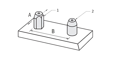
(a): component to be clamped
(b): Component with internal thread
FV: Pretensioning force (clamping force)
According to EN 14399-4 (high-strength pretensionable assemblies), the calculation can be based on the basic principle of the minimum pretensioning force level to be achieved. By reaching the minimum value, the function of the load-bearing safety-relevant connection is ensured. The influencing factors necessary for the calculation, such as the lubrication condition or the tightening process, are specified for the respective case and thus taken into account in the design.
It must be ensured that the minimum clamping force is achieved in any case, taking into account the scatter. The necessary assembly pretensioning force FVM can be determined using the tightening factors αA depending on the respective tightening procedure.
In contrast to EN 14399-4, a screw is designed according to VDI 2230 for optimum utilization of the material properties. The basis of the calculation here is 90% of the yield strength of the material. Unlike in the design according to EN14399-4, the selected tightening method is not taken directly into account in the calculation, but rather via the extent of the empirically determined dispersion through the factor αA for the respective tightening method.
According to VDI 2230, it must be ensured that the maximum pretensioning force FV max is not exceeded. To ensure this, the minimum expected assembly pretensioning force FVM min is determined based on FV max using the tightening factor αA depending on the respective tightening procedure.
Since the extent of the scatter (tightening factor αA) depends on many factors such as the lubrication condition, the thread type, the thread diameter, and also the material of the screw and component with internal threads, it is usually determined experimentally. In the past, tightening factors determined for the individual material and lubrication combinations have proven effective and are used depending on the respective operating conditions and nominal diameters.
Determining the tightening factor
\alpha_A =\frac{F_{V}\,max}{F_{V}\,min}>1
Assembly preload force according to EN 14399-4
F_{VM\,max} =\alpha_A \times {F_{V}\,min}
Assembly preload force according to VDI 2230
F_{VM\,min} =\frac{F_{V}\,max}{\alpha_A}
| Tightening factor αA |
Scatter ΔFVM / 2 · FVM mean |
Tightening method | Setting method | Notes | |
|---|---|---|---|---|---|
| 1.2 to 1.4 | ±9% to ±17% | Yield-controlled tightening, powered or manual. |
Set relative torque-angle coefficient. | Preload scatter mainly depends on yield strength variation in bolt batch. Bolts are sized for FMV min.; design for FMV max. with αA is not needed. |
|
| 1.2 to 1.4 | ±9% to ±17% | Angle-controlled tightening, powered or manual. |
Test-based setting of preload torque and angle (steps). | ||
| 1.2 to 1.6 | ±9% to ±23% | Hydraulic tightening. | Set via length or pressure measurement. | Lower values for long bolts (lk / d ≥ 5) Higher values for short bolts (lk / d ≤ 2) |
|
| 1.4 to 1.6 | ±17% to ±23% | Torque-controlled tightening with torque wrench, signal wrench or driver with dynamic torque measure. | Test-based setting of target torque on real joint, e.g. via bolt elongation. | Lower values for: Many tests (e.g. 20); low torque scatter (e.g. ±5%). |
Lower values for: • small angles, stiff joints • low hardness of mating part • non-galling surfaces, e.g. phosphated or well lubricated Higher values for: • large angles, flexible joints, fine threads • high hardness with rough surface |
| 1.6 to 2.0 (friction class B) 1.7 to 2.5 (friction class A) |
±23% to ±33% ±26% to ±43% |
Torque-controlled tightening with torque wrench, signal wrench or driver with dynamic torque measure. | Estimate target torque via friction coefficient (surface and lubrication). |
Lower values for: • measuring torque wrenches • uniform tightening • precision drivers Higher values for: • signal or break-over torque wrenches |
|
| 2.5 to 4 |
±43% to ±60% | Tightening with impact or pulse driver. | Set tool via retightening torque from target torque (estimated friction) plus margin. | Lower values for: • many setting tests (retightening torque) • horizontal tool curve • backlash-free impulse transfer |
|
What is the equivalent stress and what does this have to do with the yield strength?
The preload force is usually applied by turning the nut or screw. The tensile and torsional stresses occurring in the screw, combined as an overall stress, form the so-called equivalent stress (σred). It is a means of assessing the load on a bolted joint. The equivalent stress should be below the stress of the fatigue limit because the fatigue limit represents the highest stress that the material can withstand at theoretically infinite load cycles without failure.
As a rule, the screws used are pre-tensioned to the point that 90% of the yield strength Re is achieved. The tightening torque required for this is usually designated as MA 90. If only 70% of the yield strength Re is to be used, the tightening torque is accordingly specified as MA 70.
For screws with a specified strength class such as 12.9, the associated yield strength Re can be determined relatively easily by multiplication. In the case of strength class 12.9, this corresponds to a value of 1080 N/mm² and is calculated as follows:
Re = 10 N/mm² x value before the decimal point x value after the decimal point.
For more information on the tensile strength and yield strength of screws, check out our blog: "Calculating shear strengths and tensile strengths for screws".
Calculating the tightening torque of screws
The calculation of tightening torque for screws can be complex and depends on various factors. In the calculation, among other things, the type of thread, any possible loss of preload force, as well as the friction values of the thread and the bearing surface of the screw head must be taken into account.
At the moment of tightening the screw, not only a thread torque MG, but also the bearing friction torque MRA of the screw head on the component surface must be overcome. The tightening torque is therefore composed of a thread torque MG and a friction torque MRA. For a screw with ISO standard thread, depending on your head or Friction diameter and lubrication condition require about 80 to 90% of the applied tightening torque solely to overcome the friction between the screw head and the component surface. The friction of the thread is therefore comparatively low with a proportion of 10 to 20%.
In order to avoid the extensive calculation and determination of all values required for the calculation, a simplified approximation formula is usually used. It can often be used to determine the required values with sufficient precision.
A common method for calculating tightening torque is to use the following approximation formula.
Approximation formula with torque coefficient
M_A = F_{VM} \times K \times d
MA: Tightening torque
d: Nominal screw diameter.
K: Torque coefficient* (tightening friction factor)
* Torque coefficient K values for typical friction coefficients μG (thread) and μK (screw head or nut bearing surface) of 0.08 to 0.14 for hexagon screws with medium dimensions are in a range between 0.12 and 0.19. For the normal case with a friction value μges of approx. 0.12 (untreated, oiled metric screws), a value of K ≈ 0.17 is assumed for an approximate calculation.
In order to calculate the required tightening torque with the approximation formula mentioned here, we must first determine the desired axial force Ff (= FV) based on the parameters of the screw.
Axial tightening force and torque fatigue limit
The correct axial tightening force for a screw should be within an elastic range of approximately 70% of the nominal yield strength Re when using the torque method. The axial force (pre-tensioning force) is distributed over the entire effective cross-sectional area of the screw (AS).

Calculation of axial force
F_V = X \times R_e \times A_S
F_V = 0.7 \times 1080 \frac {N}{mm^2} \times 20.1mm^2
F_V = 15196N
Parameters of the screw in the example:
Strength class: 12.9
Nominal thread diameter: 6 mm
Thread type: Metric standard thread
Yield strength: Re = 1080 N/mm²
Effective cross-sectional area: AS = 20.1 mm² (see table)
Utilization of the yield strength: X = 0.7 (70%)
The different influencing factors sometimes have significant effects and play a decisive role in the calculation. The compliance of the materials and the settling behavior of the joint are also not negligible.
The high surface pressure in the area of the bearing surface of the screw head or the nut can cause plastic deformation and thus loss of preload. Overloading of the screw due to an excessively high tightening torque in conjunction with insufficient safety and an incorrectly selected torque coefficient or tightening method can also lead to exceeding the limit of the elastic range and thus to a lengthening of the screw with associated loss of preload, up to and including fracture of the screw.
The role of resilience for computing torque values
In the engineering sense, resilience - i.e. the ability of a material to deform or lengthen when a force is exerted - can have a significant impact on the calculation of tightening torques. If the material yields, the actual preload force can differ from the calculated preload force.
Resilience is a material characteristic. The lengthening of the screw is used purposefully to secure the threaded joint in the bore. In the range of elastic deformation, the screw can also be loosened and reused for the same joint or a new joint.
It is important to take resilience into account since an incorrect calculation can result in an inadequate preload force and thus an inadequate joint. Washers or similar design-based measures can also be taken to protect the threaded joint against unwanted loosening by using locking elements.
In our shop you will find torque wrenches to set the calculated torque correctly.
Factors affecting tightening torque
There are several influencing factors that can impact the required tightening torque. These are:
- Friction: The friction between the screw and the workpiece affects the tightening torque. Higher friction requires higher torque.
- Lubrication: Good lubrication reduces friction and can therefore help reduce tightening torque.
- Thread type: Different thread types require different tightening torques due to the thread geometry.
- Nominal diameter and length of mating thread: Larger screws typically require higher tightening torques, as well as strength classes.
- Material resilience: As noted above, the resilience of the workpiece, fasteners, and their threads may affect the required tightening torque.
- Screw quality: High-quality screws often have more consistent friction and lubrication properties. During production, the screw is handled in controlled quality windows. The calculation coefficients are in this case determined more reliably.
VDI 2230 is a guideline published by the Association of German Engineers (VDI) and a significant guideline for calculating and designing threaded joints. It provides clear guidelines and recommendations for calculating tightening torques to ensure threaded joints meet strength and safety requirements.
VDI 2230 addresses various aspects of threaded joints, including:
- Minimum cross section of the threaded joint
- Consideration of influencing factors, such as friction and lubrication.
- Takes material resilience into account.
- Recommendations for using safety factors.
In many industries and applications, VDI 2230 is used as a guide for threaded joint design, based on extensive research and real-world experience.
Calculation of tightening torque with torque coefficient and tightening factor
Another way to determine the required tightening torque of a metric screw is to calculate it based on the tensile strength of the material of the screw (σy). In combination with the effective cross-sectional area AS and the nominal diameter d, the tightening torque can also be calculated, taking into account the factors αA and K.
For the example calculation with an M6 screw with standard thread that is usually oil-lubricated at the factory and strength class 12.9, the use of a torque wrench (oil-lubricated, torque coefficient K = 0.175 and tightening factor αA = 1.4) is assumed (see the following tables). The parts to be connected are made of unalloyed steel. Other tightening procedures, lubrication conditions and materials may require different factors.
Calculating the tightening torque:
M_A = 0.35 \times K \times (1+\frac{1}{\alpha_A}) \times F_V \times A_S \times d
M_A = 0.35 \times 0.175 \times (1+ \frac{1}{1.4}) \times 1080 \frac{N}{mm^2} \times 20.1 mm^2 \times 0,006 m
M_A = 13.68 Nm
With approximation formula for comparison
M_A = F_{VM} \times K \times d
M_A = 15449N \frac{N}{mm^2} \times 0.17 \times 0.006m
M_A = 15,76Nm
Tables to support the example calculation
The use of tables can greatly facilitate calculating tightening torques and preload forces. These tables show common coefficient values for the formula that can help you calculate your threaded joints:
 for the torque coefficient table")
| Surface state | Lubrication | Method | Tightening factor αA |
|
|---|---|---|---|---|
| Bolts | Nuts | |||
| Manganese-phosphated | Untreated or phosphated |
with oil or MoS2 paste |
Torque wrench | 1.25 |
| Untreated or phosphated |
Torque wrench | 1.4 | ||
| Torque wrench with force limit | ||||
| Impact wrench | 1.6 | |||
| Untreated or phosphated |
Untreated | Unlubricated | Torque wrench | 1.8 |
| Torque wrench with force limit | ||||
| Bolt surface and surface treatment |
Torque coeff. K |
Material combo for clamped part (a) and material (b) of internal thread (a) - (b) |
|---|---|---|
| Steel bolt Black oxide Coated, oiled |
0.145 | Heat-treated steel (35HRC) - Cast iron Cast iron - Cast iron Stainless steel - Cast iron |
| 0.155 | Carbon steel - Cast iron Heat-treated steel (35HRC) - Carbon steel Heat-treated steel (35HRC) - Heat-treated steel (35HRC) Cast iron - Carbon steel Cast iron - Heat-treated steel (35HRC) |
|
| 0.165 | Heat-treated steel (35HRC) - Stainless steel Cast iron - Stainless steel Aluminum - Cast iron Stainless steel - Carbon steel Stainless steel - Heat-treated steel (35HRC) Stainless steel - Stainless steel |
|
| 0.175 | Carbon steel - Carbon steel Carbon steel - Heat-treated steel (35HRC) Carbon steel - Stainless steel Aluminum - Carbon steel Aluminum - Heat-treated steel (35HRC) |
|
| 0.185 | Heat-treated steel (35HRC) - Aluminum Cast iron - Aluminum Aluminum - Stainless steel |
|
| 0.195 | Carbon steel - Aluminum Stainless steel - Aluminum |
|
| 0.215 | Aluminum - Aluminum | |
| Steel bolt Black oxide Coated, dry |
0.25 | Carbon steel - Cast iron Heat-treated steel (35HRC) - Cast iron Cast iron - Cast iron |
| 0.35 | Carbon steel - Heat-treated steel (35HRC) Heat-treated steel (35HRC) - Heat-treated steel (35HRC) Cast iron - Carbon steel Cast iron - Heat-treated steel (35HRC) Aluminum - Cast iron |
|
| 0.45 | Carbon steel - Carbon steel Heat-treated steel (35HRC) - Carbon steel Aluminum - Carbon steel Aluminum - Heat-treated steel (35HRC) |
|
| 0.55 | Heat-treated steel (35HRC) - Aluminum Cast iron - Aluminum Aluminum - Aluminum |
These tables are examples only and may vary depending on the specific application. It is important to select the right values based on your situation.
| Coarse thread | Effective area AS in mm2 |
Strength class | ||||||||||||||||||||||||||||||||||||||||||||||||||||||||||||||||||||||||||||||||||||||||||||||||||
|---|---|---|---|---|---|---|---|---|---|---|---|---|---|---|---|---|---|---|---|---|---|---|---|---|---|---|---|---|---|---|---|---|---|---|---|---|---|---|---|---|---|---|---|---|---|---|---|---|---|---|---|---|---|---|---|---|---|---|---|---|---|---|---|---|---|---|---|---|---|---|---|---|---|---|---|---|---|---|---|---|---|---|---|---|---|---|---|---|---|---|---|---|---|---|---|---|---|---|---|---|
| 12.9 | 10.9 | 8.8 | ||||||||||||||||||||||||||||||||||||||||||||||||||||||||||||||||||||||||||||||||||||||||||||||||||
| Yield load N |
Preload N |
Torque Nm |
Yield load N |
Preload N |
Torque Nm |
Yield load N |
Preload N |
Torque Nm |
||||||||||||||||||||||||||||||||||||||||||||||||||||||||||||||||||||||||||||||||||||||||||||
| M 3 | 5.03 | 5517 | 3861 | 1.67 | 4724 | 3312 | 1.47 | 3214 | 2254 | 0.98 | ||||||||||||||||||||||||||||||||||||||||||||||||||||||||||||||||||||||||||||||||||||||||||
| M 4 | 8.78 | 9633 | 6742 | 3.92 | 8252 | 5772 | 3.33 | 5615 | 3930 | 2.25 | ||||||||||||||||||||||||||||||||||||||||||||||||||||||||||||||||||||||||||||||||||||||||||
| M 5 | 14.2 | 15582 | 10907 | 7.94 | 13348 | 9339 | 6.76 | 9085 | 6360 | 4.61 | ||||||||||||||||||||||||||||||||||||||||||||||||||||||||||||||||||||||||||||||||||||||||||
| M 6 | 20.1 | 22060 | 15445 | 13.52 | 18894 | 13220 | 11.56 | 12867 | 9006 | 7.84 | ||||||||||||||||||||||||||||||||||||||||||||||||||||||||||||||||||||||||||||||||||||||||||
| M 8 | 36.6 | 40170 | 28116 | 32.73 | 34398 | 24079 | 28.03 | 23422 | 16395 | 19.11 | ||||||||||||||||||||||||||||||||||||||||||||||||||||||||||||||||||||||||||||||||||||||||||
| M10 | 58 | 63661 | 44561 | 64.97 | 54508 | 38161 | 55.57 | 37113 | 25980 | 37.83 | ||||||||||||||||||||||||||||||||||||||||||||||||||||||||||||||||||||||||||||||||||||||||||
| M12 | 84.3 | 92532 | 64768 | 113.68 | 79223 | 55458 | 97.02 | 53949 | 37759 | 66.05 | ||||||||||||||||||||||||||||||||||||||||||||||||||||||||||||||||||||||||||||||||||||||||||
| M14 | 115 | 126224 | 88357 | 180.32 | 108084 | 75656 | 154.84 | 73598 | 51519 | 104.86 | ||||||||||||||||||||||||||||||||||||||||||||||||||||||||||||||||||||||||||||||||||||||||||
| M16 | 157 | 172323 | 117982 | 281.26 | 147549 | 103282 | 241.08 | 100470 | 70325 | 163.66 | ||||||||||||||||||||||||||||||||||||||||||||||||||||||||||||||||||||||||||||||||||||||||||
| M18 | 192 | 210739 | 147519 | 387.1 | 180447 | 126312 | 331.24 | 126636 | 88641 | 232.26 | ||||||||||||||||||||||||||||||||||||||||||||||||||||||||||||||||||||||||||||||||||||||||||
| M20 | 245 | 268912 | 188238 | 548.8 | 230261 | 161181 | 469.42 | 161592 | 113112 | 329.28 | ||||||||||||||||||||||||||||||||||||||||||||||||||||||||||||||||||||||||||||||||||||||||||
| M22 | 303 | 332573 | 232799 | 746.76 | 284768 | 199332 | 638.96 | 199842 | 139885 | 448.84 | ||||||||||||||||||||||||||||||||||||||||||||||||||||||||||||||||||||||||||||||||||||||||||
| M24 | 353 | 387453 | 271215 | 948.64 | 331759 | 232231 | 812.42 | 232819 | 162974 | 570.36 | ||||||||||||||||||||||||||||||||||||||||||||||||||||||||||||||||||||||||||||||||||||||||||
| ||||||||||||||||||||||||||||||||||||||||||||||||||||||||||||||||||||||||||||||||||||||||||||||||||||